ANSWERS
1- What Software and Hardware
is required to run PADEE?
Currently PADEE needs Windows, preferable version 10 or 11 and Autocad (2006 up to 2023) or Bricscad (V19 to V22) or ZWCAD (2022).
The hardware required is depending on Maps size. A good computer can open the map in CAD and allow you to work with them without any delay.
Actually a commercial computer with Windows 10 or Windows 11 can handle a city without any problem,
but remember CPU speed and RAM resources allow to work faster in CAD. Please see requirements detail in our web page. https://padeepro.com/padeeing.html
2- In COMMASW: Another person
have enter new materials on his computer, my question is: Can i,
with pen drive or shared network drive, bring that information to my computer
and keep working on that; the procedure is normal or is there a special way to do this?
If you are working as stand alone user, the easiest way is to manually copy the
databases, listed below, found the folder c:\COMWIN:
- MAT_XXX.DBF
- UNI_XXX.DBF
- PRAR_XXX.DBF
Where XXX is the short name entered at the beginning of the program. For example DAT
You should also delete all *.IDX files. These are automatically generated again when
you start the program COMWIN
If you are working with prices unit must follow the same procedure with the
following databases:
- PER_XXX.DBF
- EQU_XXX.DBF
- MUPU_XXX.DBF
- PARU_XXX.DBF
3- How can
I change the material prices quickly using scaling formulas?
To change materials prices, labor and equipment quickly please use the COMMASW program
There are two forms:
- When a new price area is created, the program asks if user want to use a
previous area multiplied by a constant factor.
- In each of the menu there is an Export option. With this option you can
export the databases to EXCEL and this program can sort by material type and
multiply it price with individual factors or materials group.
Be especially careful, please follow the next sugestions:
- If you are creating a new area. Create it before exporting
- If you are suing Excel, do not change the size and order of the columns.
Users may use more columns to the right side of
the existing columns to perform calculations and then copy with the option of
"values" in the "price" column, these new additional columns will not be taken into account.
- When saving changes in Excel, please select the option to keep the current format (.cvs).
- The spreadsheet is automatically deleted after updating the database. If you want to keep the
spreadsheet for future revisions it may be copied with another name before
importing.
4- Is COMWIN multiuser?
Yes it is. The COMWIN program must be installed on a client machine and then copy the folder to a directory
named ComWIN on the server. On the server user must create a shared folder with a letter assigned for example w:\ComWIN
On all the client's computer, the program must be installed to introduce the
access key but then you can delete the executable and make a "direct access"
to the program file in the server. Later you can edit existing shortcuts and change
where it says c:\ComWIN to w:\ComWIN.
You can share the fixed data or the "Hard Disk Data" but not the
works files. The works files can be also created on the server (for easy backup
purpose), but in a different folder, or in each client hard drives. Also pen drives are allowed.
When the COMWMAS is used in multiuser mode, other users can not use the database
files: materials, construction units and equipment with the same name.(Ie:DAT)
5- COMWIN results prsent duplicate construction units
and double cost. How do I fix this?
At starting COMWIN databases in the folder C:\ComWIN are combined with the database in the folder WORKS.
These databases are called exactly the same but they are in different folders.
The idea is to keep the database and prices updated and locked in application folder
ComWIN and if any particular work requires a different construction unit or
change the content of one construction unit these change should not affect
other works and this new construction units or materials are created in the
WORK folder. Work database's folder should be empty is no new material or cost
is entry for a particular work.
If by mistake the database in c:\ComWIN is copied in the folder works. At the
start of the application the two databases will join materials and
constructions units producing duplicates.
To solve this problem you can proceed as follows:
- Delete all files that have .IDX extension. If you can not see the extensions, check the folder options
to see the extension of all files.
- Open a new folder where works files will be located
- Copy files that begin with "P" and "U" followed by the code of the work
- DO NOT COPY THE MAT_XXX,UNI_XXX, etc. FILES
- Run the BUDEDWIN application and change the working directory to the new location\folder. (It will create
the files materials and units again)
- Ready.
If after this procedure material or construction unit are
missing, check the folder of previous works and entry the data again. If many
units are missing materials and proceed as follows:
- Change the in the work folder the name of the original databases MAT_DAT, UNI_DAT,
etc to a new shot name for example MAT_DA2, UNI_DA2, data etc.
- Start COMWIN please change the data base short name to DA2 and when It ask to create files;
say NO and when it ask to working with WORK data; say YES
6- In PNAP module, after feeder identifying, it says: "Don't have ORDERING",
what should I do?
"Don't have ORDERING" message is because there was a problem with identifying procedure. Please check the network topology for this feeder.
User must verify the drawing, looking for:
- Repeated sections
- Misplaced switches or disconnectors.
- Loops or rings.
- Others will be explained in the following paragraph
Repeated or overlap sections: When making the drawing, some times one
line is drawn twice or is over another. The detection could be done opening feeder
by parts to achieve isolating and identifying the part with problems.
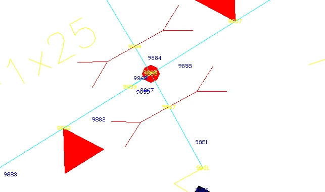
You should look for sites where several identifications numbers look very close
each other and touching the lines with the mouse to verify each lines blue dots
or "GRIPS".
If the numbers of nodes and sections font are very large and are mounted on top
of each other, you can reduce the font size using the Utility Macro-> SCBL. Touch
a yellow number and enter, type 0.2 and then type ALL. The same procedure is
performed with blue numbers.
In the next figure an overlap sample is presented.
If loads and sections numbers are removed and touch with the mouse line on the
right, the figure may look like the following:
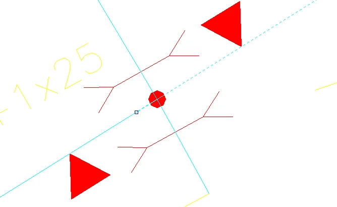
Please note that the end point of the line is a point shortly after the intersection.
However, if the left side line is touched the following figure is showing the
problem:
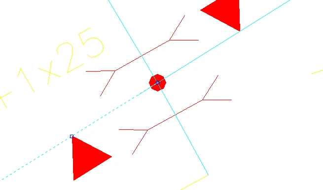
User may notice that the line on the right side ends just at the intersection. In this case the left
line is overlapping the right line
To solve this problem, you must touch the right line and move the GRIP to the
end, of the left line using the snap command "endpoint".
Repeated:When a repeated section shows that the numbers of the sections are overlapping each other
Loops:When a circuit is closed to himself doing a loop or ring. Here is an
example:
Loops can not be easily detected, so it is recommended to "cut" by half the circuit and try to identify. If the identification
is correct, it means that the error found after half of the circuit. It should
proceed iteratively to reduce the area where the error located. In some cases
it is quite difficult so users have to have some patience as it usually is an
error while surveying the network in the field.
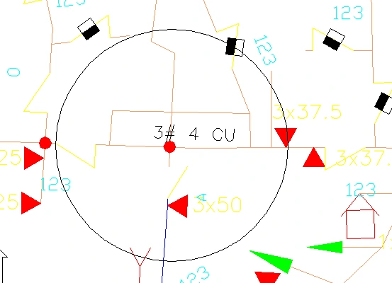
Problem for more than 4 branches at a node. Padee allows up to four
branches starting from a node.
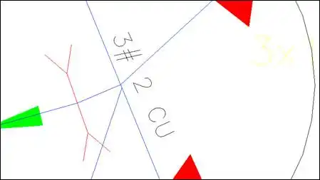
In the figure below is a sample of this problem. The node enclosed within the
circle, has five (5) branches. One section must be separated a little bit.
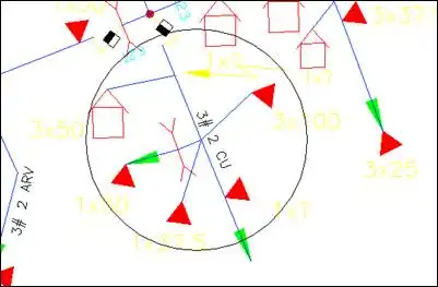
The following figure shows how the drawing should be to correct the problem.
7- ANALYZING: When I run the PANP ANALYZE option, sometimes
shows the following: READING RESULTS: NOT COMPLY, KVAINT: 7990 DEM: 8808 3730KVAR ... What does this expression
means?
When you run ANALYZE and select the option "Draw Results", the program
colors the circuit that does not meet the established criteria (The criteria is
enter in the menu that appears when this option is selected, to color the part
when the voltage drop maximum criteria or maximum permissible conductor load is
exceeded). In addition the entire length of the circuit, which does not meet
these criteria, either by voltage drop or load it is presented in the command
line.
8- One error messages that gives the program after running it is that the
circuit has no data, why does this?, if the data were inserted by selecting the
first line coming out of the S/S.?
Feeder's data must entered in line that is attached to the
substation, if you use Macro-> XD and you touch the line coming out of the
substation you'll see no data. However if you touch the long line that goes to
the right you will see that if you have data feeder name, current, etc., the
program will give the error: "Can't find the Substation".
The data in this last line should be deleted with MACROS-> XD_LIMP. The Data
should be placed back on the line that is near and "stuck" to the substation.
This also happens when a line that already has feeder's data and
a new switch is inserted. The two lines at both switch ends will have the same
data and information appear repeatedly in MACROS-> SEARCHS-> SEAFED
Use the MACROS-> XDLIMP program to remove the feeder's data in the unwanted line.
9- What does this Message means: "Substation's name
was not found in Step 2 for the feeder xxx"
This happens when you haven't entered the feeders data, namely:
number, name, current etc. to the line that this just stuck to the substation,
it can also occur when a switch is inserted right in the first line leaving the
substation. The line is spliced with the same duplicate information on either
side of the switch. See item 7.
10- When I put capacitors banks the result is equal
to the previous one. (Without capacitors)
The right procedure to run capacitors process is as follows:
- Run the process Identify, Load Place, Assign, Analyze.
- Run the CAPACI option
- Verify the location of the capacitors banks and place them using the automatic
library INSBLO.
- Run Identify and Analyze without using Load Place option.
Most problems happen because LOAD PLACE process is run with the same current and
power factor at the substation. Please note that in the real world, when the capacitors
are placed in a feeder, the current is reduced and power factor improvement in
the output of the substation.
When users use the assign loads option there is not need to Load Place again.
If the user wishes, after the last analysis, the current and power factor presented in the analysis output report can be noted and modify the feeder's data. Thus
you don't have to be carefully in the future. (Results may vary by 1% approx.)
11- I have a substation 115/34.5 KV, Mumbay,
which feeds another substation 34.5/13.8 kV (Hospital). It is required to run this 34.5 kV line in
PADEE, but the program gives me error, because it sees the substation Hospital
as a source instead as a load. How can I do? this (See next figure)
The following figure shows how users tend to draw the map
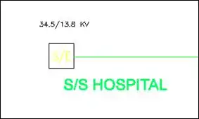
This figure above is incorrect. The symbol used is taken as a
source. The correct way to express the network in this case is as shown in the
following figure:
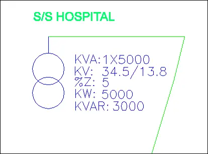
The symbol may befound in the INSSID library. Please make sure the block is in
layer TRANS layer, since this library is not the smart one.
If the substation load in question also serves as a source for 13.8 kV feeders,
you may represent it with UNIONS, which is also found in the INSSID library. An
example is shown in the figure below.
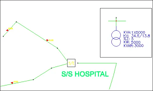
Please notice that 34.5 kV line coming from the left side does
not touch the symbol of the substation. Furthermore the connection block has
two letters, where it starts and where its end. The 34.5 kV line have one
letter and the end at the detail entrance is the other letter.
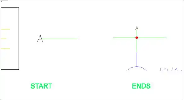
The distance between the two "A" will not be taken
into account for the analysis, so you place the symbol where is easy to see.
12- In PANP, module IDENTIFY option.. I get the error: "Failed to open the file
C:\PADEE\TEMP\CARNOD.DAT". How can I fix this?
The PADEE needs to write temporary files on the folder
c:\padee\temp or under the drawing/temp (User is allowed to change the temporary folder location, ask
Jorge Matheus)
Please check user permissions to see if you can write freely in the c:\PADEE
and its sub folders. You can perform a test trying to create a text file in
that directory. If the creation of the text file can be done without problems
then you should exit AUTOCAD and delete all files contained in the
C:\PADEE\TEMP or under the drawing\temp folder, which may have been corrupted by power failure or other
previously problems.
13- In IOP module, when I do an operation or maneuver,
the program gives me an error and keep the switch in the original position (as it was).
To use the interrupt and operations module, it is necessary that all feeders are properly identified,
Load placed, and load assigned. Preferably with the "Process All" PANP option.
If the feeders are not processed yet, to change the position of a switch, use
the switch library INSSWI;

press the Edit button and choose the desired switch type and position.
Note that IOP module should only be used when you are simulating network
operations or maneuvers, the network must be completed and without errors. If
on contrary it is being modified to incorporate more network load or to
simulate a planning condition INSSWI library to change the position of the
switch and then indentify and ANALYZE. Thus it is not necessary that the
circuits are completely "identified" to make changers in the network
or analyze part of it.
14- What is for the option ASSIGN LOAD?
After running IDENTIFY and LOCATE LOADS, The load demand for each transformer can be write on their drawing's blocks, after doing
this you may change the feeder configurations as it was originally when the field survey was done.
This option is used when capacitors are placed, removed or added load to a
feeder. These actions increase or decrease the current in the feeders involved
in the operation, but the change is not made in the feeder's data. If you run
LOCATE LOAD again, without changing the current feeders, the utilization factor
will be modified but the currents remain almost the same.
Once the load is distributed, and users assure these analysis is within the
expected parameters (Fu = 0.3 for rural loads and FU = 0.6 for urban areas,
approximately) the load should be assigned. This way you can make operations
without thinking that the currents in feeders vary in each operation. The
currents resulting from the analysis will be presented in the summary.
The IOP system is for use in the Distribution Operation Center D.O.C. the
circuits are completely surveyed and analyzed. When the engineer ensures that
the map is well built and drawn, then proceeds to make a final load
distribution or allocation and then recorded into the blocks attributes. CAD
file must be saved and will be available for others operations.
As general rule after the model is setup user shouldn't use Identify, Load Locations and
Load Assign options again.
If you want to change the feeder's configuration permantely, not in the DOC, user may use
the same routine that is used for switch insertion INSSWI and the MODIFY button.
15- When the program runs IOP gives the message "Error in BUSORD"
As mentioned above the IOP requires that all feeders in the map are processed without errors. When this
message appears is because the nodes or sections in the database are not "right".
When you run the "Process all" option, the database is restarted and filled with the correct information. This could
happen if user don't save the CAD file after and operation or maneuver.
16- Inserting a switch or cut-out in a feeder the program ask a about an ID Number. What if i put "0" (zero) to all of them?
What consequence it may bring?
Switches and other disconnect equipment need to be identified to reduce possible maneuver mistakes. When the
maps are used to perform operations on the DOC each switching points of the network must be identified without any repetition.
The identification may be geographical or any other that way the user's desire. If you do not have these
data at the time the network is drawing, it is usual to leave it to 0. But at the time the actual identification numbers
is placed in the field users should make the change in the map and enter the right identification number
17- I need to change the color of the transformer load, because when printing
the map on white paper the yellow does not Contrast and it is not well displayed
The best way to do this is using printing pens. At plotting time using the PLOT command pen style appears. You must edit these pens.
In the PEN table the thickness and color for each pen is available. Search for the Yellow pen and select
to print in black.
Editing pen's table tells the plotter the color and thickness to give better "expression"
when printing and latter making copies. In the user manual a pen table is
indicated for the colors that are predefined in the PADEE. This table is copied
below.
You may start with the default pen file "monochrome"and edit them to
give thicknesses that indicate in the table below. If you are printing in black
and white it should be noted that each color would correspond to the BLACK. But
if user is printing in color, each color will print with the same as is
displayed in the screen, except yellow color that it will be changed to BLACK.
	COLOR				PEN THINKNESS				LEROY EQUIVALENT
	Magenta					0.15 mm					0000
	White, Cyan					0.25 mm					000
	Yellow					0.35 mm					1
	Red						0.50 mm					2
	Green						0.70 mm					3
	Red ( 010 )					0.60 mm
	Crem (021)					0.60 mm
	Brown (025)					0.60 mm
	Orange (30)					0.60 mm
	Yellow ( 050 )				0.60 mm
	Olive Green (054)				0.60 mm
	Ligth Green ( 90 )				0.70 mm
	Dark Green(104)				0.60 mm
	Aquamarine (121)				0.60 mm
	Ligth Blue(130)				0.60 mm
	Dark Blue (160)				0.60 mm
	Violet (212)					0.60 mm
Pen file can be save and keep for latter use. The file also can be
exported and imported to other machines or other CAD versions, but some time
different plotter brand don't allow this.
Another way is to use a PADEE's utility, you have to manually load it.
(load "c:/padee/lisp/GATCHA")
Luego
Command: gatcha
Block name specification <*>: Ecadtr01
Attribute value specification <*>: CAPACIDAD
Attedit: Style/Layer/Height/Oblq angle/Rot angle/Color/<eXit>: C
New value: 1
Working.....................
Attedit: Style/Layer/Height/Oblq angle/Rot angle/Color/<eXit>: X
This must be done for each block, so you better use the other
option that is only needed once and the maps are printed with expresion.
18- When PADEE is run the message "ERROR Writing No 2" is presented. What does it means?
This error occurs
because the user does not have permission to write on the PC's hard drive.
Usually it occurs during installation, but can also occur if any of the users
modify their local privileges.
You should check; if you can write freely over the following folders copying
any file (for example a text file) in the folder c:\padee and then delete it
again. If you can't do it is because your PC has restricted access to your
hard disk.
You should also check that you have free access to the Windows folder by
repeating the same process above in this folder.
It is recommended that the PADEE's user has Local administrative privileges on
their PC to work smoothly, otherwise should "share" the folder
C:\padee and C:\ Windows with all its subfolders.
19- UPDATING tells me I can not connect to the FTP server
The UPDATE application needs to connect through port 21 & 22 to check which
updates are available and downloaded the necessary updates. Also it required to
connect to the page https://padeepro.com and
http://matmor.dynu.com
20 - SGMAP: No "Google Map" image is presented
The SGMAP option requires these several conditions are met:
- The map must be georeferenced in UTM coordinates. (REGVEN) or state plane for USA.
-
- Must correctly choose the UTM zone or state plane for USA or map's images will be presented correctly
- The user should be able to access the Google Map application on Internet
- The user should be able to run JavaScript
- The https://maps.google.com/maps/api/ application API must be accessible to the user's machine.
-
- The firewalls or antivirus firewalls must allow execution of the program c:\ padee\PFIE\track.exe
Rarely the map of a town or city can be found between two UTM zones, so the
program could not show correctly the Google MAP image or presented wrongly. The
program tries to make an approach in these cases, for ease of use to the user.
User must select the UTM zone that covers the most part of the city.
21- SGMAP Google display a SCRIPT error or other error message
Every 3-month Google changes their API which are the main resource to use their maps. Most of the times, it doesn’t affect our application,
but when it does an update will solve the problem. Also you may use option "B" at SGMAP beggining to use Bing Map from Micrososft instead of G for Google..
Update a least every 3 months or once a month is recommended
22- When the PNAP is running the "exceeded the maximum number of nodes" message appears
In the PNAP Options menu on the left side there is an option that says "Start from Zero".
Simply select this option to restart the nodes and sections count.
The PADEE has up to 1000 feeders 5000 nodes each. Which it is enough to analyze the vast majority of the cases.
This amount can be extended to a much larger number, but a higher processing speed computer is required, in addition
to having enough memory capacity to handle larger CAD maps.
In any case it is advisable to work by city or state.
23- When I'm Identifying the message is not in line z = 0 appears. How to solve this?
This happens when working on a road map with elevations or mapping, IE 3D. Possibly some component of the network is traced and inadvertently left with an elevation.
In other words; the coordinates of the origin ar end of the line are not zero as in the following example:
(Source 10,10,2.3) ----------------------- (end 15,10,2.7)
The value 2.3 and 2.7 correspond to the elevation or Z value. This can generate an
error in the calculation of the length and thus get the error message.
24- How does PADEE model "Distributed Generation"?
There are two ways:
- When there are several generators in a single point. It is modeled like a substation
- When it is a "relatively small" generator installed on a circuit
After simulate the feeder, (identify, allocate and assign) insert a block generator using INSSID
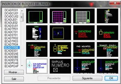
It is place in the map like a transformer and generating data that will contribute to the feeder with negative values are filled.
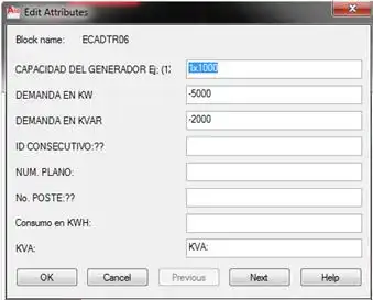
Then make a new simulation identifying and analyzing without load location and Load assign.
25- When I'm updating I get the
error "Can not connect to the FTP matmor.dynu.com or padeepro.com
The reference problem is basically due to users restrictions to browse the Internet freely.
Since the restriction is done on their servers and/or user's equipment, is
difficult to raise solutions. However given the recent tests conducted with staff from various regions ATIT, here is a list of some of
the points that users must check:
- Should be able to freely access the page http://matmor.dynu.com & https://padeepro.com
In some cases it was necessary to add this address to the list of addresses allowed by the server in the region.( check the white lists)
- In other cases also they had a problem with the DNS service. It is very recomended to include several dns as google dns 8.8.8.8 and others
- Useres have free access read and write to the folder c:\padee
An easy test is to create a text file in the folder c:\padee and then delete it. If the creation and deletion of the file is possible, they should have free access.
- It is also necessary for the user or server allow access to the FTP protocol and port 21 & 22.
If it is not possible to have a free Internet the connection, a "BAN" or "Pendrive MODEM type" with connection via GSM phone could work.
In 99% of cases the problem was solved after adjusting user connections.
We have several servers in several countries so there is a very small chances that problem is on our side.
26- To install the new PADEE 2023 version, should I uninstall the older version?
It is no necessary. The new version Will be installed overwriting the old files in the same folder.
But please remember that the new version will requiere new compiler system files, so the use of the setup Disk is necessary
For the other program like COMWIN or MAINTENANCE the data base is 100 % compatible so if you have changed these databases or create new projects, do not overwrite them.
27- After finishing setup NO PADEE menus appear in Autocad. How to solve this?
If after installing PADEE no menus appear in CAD, please sun the application c:\padee\Autocad\INSCADPA.exe
If after running this application the menus didn't appear, carefully check whether an error occurred during the execution
of the application INSCADPA.exe. If an error is observed please make print screen image and send it to
jorgematheus@gmail.com . But if no error appears, please search the folder for the file:
c:\padee\autocad\Acadver.sal and send it to jorgematheus@gmail.com
If you don't see your question in this document, please send the question with examples and images by email, and we gladly answers your questions